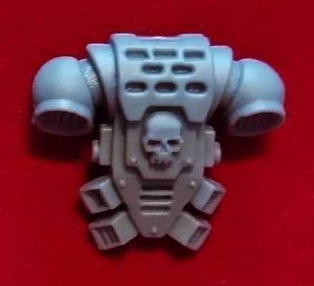
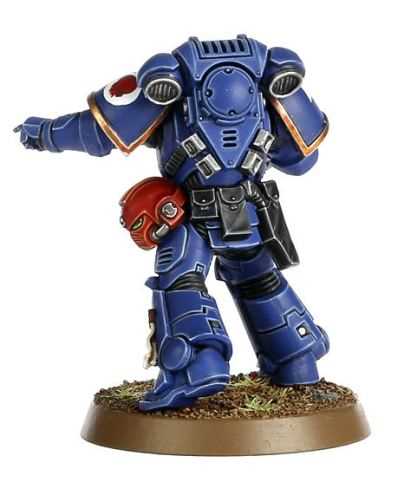
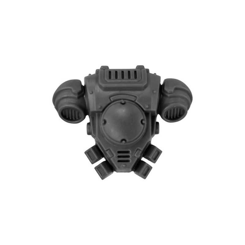
Recommend selecting a propulsion-equipped pack when mission profile includes long-range assault, rapid vertical mobility, or heavy-kit transfer. Aim for a thrust-to-mass ratio of at least 1.2:1; prefer 1.5–2.0:1 during repeated hops. Minimum primary energy capacity: 20 kWh chemical equivalent with sustained-output rating near 5 kW continuous; compact fusion cores: plan on 50–200 kWh depending on mission endurance.
Key modules include: propulsion (thrust-vectoring microjets or plasma turbines), primary power cell with quick-swap interface, thermal management featuring an active coolant loop and heat sink rated at 10 kW continuous dissipation, sealed life-support cassette with CO2 scrubber and oxygen reservoir supplying 8 hours at rest, distributed ammunition stowage integrated into chassis, encrypted comms with mesh relay plus secondary low-latency link, and external mounting points compatible with standard armor bolt patterns.
Pre-sortie checklist: charge primary cell to ≥95%; inspect harness straps and quick-release latches; tensile strength threshold: >1,200 N; verify seal integrity under 1.2–1.5 bar positive pressure; conduct idle-thrust test for 5 minutes and confirm actuator alignment within ±0.5°; confirm coolant pressure and flow, run encrypted comms loop, and perform emergency-ejection dry run. Replace cells after approximately 300 full cycles or at first signs of capacity loss > 15%.
Mission-match guidance: lightweight reconnaissance variant mass 12–15 kg, endurance 30–45 min, cruise speed up to 25 km/h, payload allowance 10–15 kg. Heavy assault variant mass 35–50 kg, endurance 10–20 min, payload allowance 40–60 kg, includes reinforced plating and integrated ordnance mounts. Select a configuration by weighing endurance, protection, and mobility; expect weight penalties to scale nonlinearly with added armor and ammunition.
How a Torso-Mounted Power Unit Supplies and Regulates an Astartes Power Core
Use a three-tier power-management stack: primary fusion generator rated 18–30 kW continuous with 90 kW peak (15 s), secondary supercapacitor bank sized ~1.0 MJ usable, tertiary micro-reactor governor with sub-millisecond solid-state switching and redundant failover channels.
Primary cell connects to a superconducting bus through magnetically coupled feed pistons and high-current isolation relays; supercapacitors accept transient loads while DC–DC converters present stabilized 28–48 V rails for servo-actuators and 5–12 V rails for sensors. Active pulse-width modulation at ≥2 kHz keeps voltage ripple <200 mV. Flux and Hall sensors sample at 8 kHz, feeding closed-loop PID controllers that adjust coil drive and suppress surges within 50 µs.
Power routing uses segmented harnessing with bi-directional contactors. Normal operation routes generator → bus → distribution manifold → subsystem trunks. Surge handling switches to cap bank via ultra-fast MOSFET stacks; persistent overloads trigger staged shedding: non-critical weapon mounts first, then auxiliary life-support, preserving core locomotion and shielding for a minimum 90 s under degraded power.
Thermal control employs dual-phase coolant loops: primary loop evaporates fluorinated coolant across reactor jackets at 35–70 kPa, secondary loop transfers heat to graphite radiators rated 4–6 kW/m². Emergency venting engages at 120 °C core skin; pressure relief opens at 2.5 MPa, dumping heat into ablative panels. Maintain coolant flow 4–8 L/min with pump redundancy 1:N and automatic crossover within 250 ms.
Protection layers include current limiting at 1.2× nominal, thermal derating above 85 °C, and active capacitor balancing using servo bleeders. Overcurrent routes to sacrificial resistive loads or kinetic dampers to protect reactor magnets. Telemetry logs at 1 kHz into ECC-protected memory; fault logic isolates faulty channels and reconfigures remaining channels within 100 ms to sustain critical movement and target acquisition.
Installation and maintenance guidance: route superconducting lines inside the armored spine with ceramic insulators every 120 mm and tensile-rated couplers on manifolds. Service intervals set at 500 operational hours or after 12 high-stress sorties; calibrate flux sensors, rebalance capacitor stacks, replace primary seals and absorbent matrices at each major overhaul. Field repair kits should include spare MOSFET stacks, two pre-charged cap modules, and a portable coolant reclaimer rated 10 L/min.
Life-support, thermal control & atmospheric filtration in dorsal modules

Install redundant CO₂ scrubbers, dual oxygen sources and a sealed 2‑hour breathable-air reserve.
Primary breathable-gas delivery: high-pressure oxygen cylinders at ~200 bar paired with a chemical oxygen generator as backup. Nominal supply targets: oxygen concentration 21% ±1%; CO₂ kept below <5,000 ppm (comfort target <500 ppm during prolonged operations). Nominal ventilation flow: 40–60 L/min continuous; surge capacity 120–180 L/min during peak exertion. Emergency sealed reserves sized to sustain a 60 L/min metabolic load for a minimum of 120 minutes.
Atmospheric purification uses a staged approach: coarse cyclone/prefilter (removes >10 µm), fine particulate stage (HEPA H14, 99.995% at 0.3 µm), activated carbon bed sized by expected VOC load (typical mass 300–800 g per mission profile) and an oxidation catalyst for CO reduction. Solid CO₂ chemical sorbents (lithium hydroxide cartridges or solid amine beds) placed in parallel with regenerative molecular-sieve scrubbers handle rapid CO₂ excursions. Sensors: NDIR CO₂ (0–50,000 ppm, ±50 ppm), electrochemical O₂ (0–25% vol, ±0.1%), PID for VOCs; automatic control logic switches scrubbers and alarms at programmed thresholds: O₂ 5,000 ppm triggers scrubber priority and crew alert.
Thermal control blends passive and active elements. Expected heat rejection range depends on activity: 200–800 W. Short-pulse absorption uses phase-change modules (PCM) with latent heat ~150–220 kJ/kg; typical PCM mass 1–3 kg absorbs high-load spikes for 10–30 minutes until loop cool-down completes. Continuous rejection uses a pumped liquid loop (propylene-glycol/water 30–40% mix) with flow rates 0.5–1.5 L/min, heat exchangers integrated into dorsal radiator panels and heat pipes coupling internal hot spots to external fins. Target internal suit interface temperature setpoint: 28°C ±2°C at the skin layer; coolant loop delta-T maintained near 8–12°C.
Mechanical subsystems: dual blowers each rated 70–150 L/min with crossfeed valves and independent power taps; particulate filter pressure-drop kept under 200 Pa at nominal flow to avoid excessive blower load. Maintenance intervals: prefilter wash every 10–20 hours in high-dust environments, HEPA replacement every 50–200 hours depending on particulate loading, activated-carbon bed replacement after adsorption capacity reached or every 100 hours. Use a pressurized foam tool such as best car wash foam cannon for pressure washer to flush external particle screens during field maintenance.
Control electronics: redundant microcontroller units with watchdog timers, closed-loop PID on O₂/CO₂ setpoints, sensor fusion to detect sensor drift. Hard fail actions: automatic suit pressurization to safe partial pressure, seal isolation of contaminated zones, activation of chemical-scrubber bypass and audio-visual crew alarms. Mass budget guidance: combined life-support, filtration and thermal hardware mass typically equals 25–40 kg depending on mission duration and peak thermal load; design trade-offs favor modular replaceable cartridges to minimize downtime between sorties.
How jump packs enable controlled leaps and operational limits

Recommended maximum continuous burn: 6–8 seconds at 160–220 kN total thrust while lifting a 120–140 kg armored trooper with full combat load.
Lift and control rely on three subsystems: vectored primary nozzles with ±15° gimbal, lateral reaction-control thrusters set at 6–8 kN each, and a gyro/IMU suite that maintains attitude with <30 ms latency. Combined control bandwidth yields pitch/roll rates up to 60°/s and yaw authority sufficient to correct ±10° wind gusts within one second.
Typical fuel mass: 8–12 kg of high-energy propellant. Consumption rate at full power: 0.9–1.3 kg/s; this produces a practical single-engagement ceiling of 6–12 s at max thrust. Recommended operational envelope uses 40–70% thrust for routine leaps, extending endurance to 12–20 s and improving landing margin.
Vertical performance: initial vertical acceleration commonly 3.5–6 g at nominal load; short bursts up to 10–12 g permissible with neural dampeners and reinforced vertebral support. Horizontal dash speeds reach 40–80 km/h during ballistic transition when vectored thrust is combined with torso pitch. Maximum safe deployment altitude typically 200–400 m above launch point; thermal dissipation and sensor degradation limit effective operation beyond ~1,000 m.
Thermal and structural limits: nozzle throat temperatures approach 1,200–1,500 °C at sustained full-thrust; heat sinks store ~12–18 MJ before performance throttling. Duty cycle guidance: 8 s full-thrust then minimum 60 s cooldown under grounded conditions; repeated short hops (≤4 s each) allow cumulative sorties with reduced cooldowns but increase inspection frequency.
Environmental constraints: crosswinds above 18 m/s degrade control authority and significantly increase flare-to-touchdown workload. Urban canyon use increases risk of plume impingement and blast reflection; maintain minimum lateral clearance of 6 m from tall obstacles during vertical ascent and 12 m during lateral transition.
Maintenance and preflight checks: verify propellant pressure ≥9 MPa, inspect nozzle seals and articulation bearings every 10 sorties, replace thermal coatings after 30 high-thrust engagements, run gyro spin-up and flight-computer self-test (complete cycle <15 s) before each sortie. Recommended reserve: retain 20–25% propellant post-landing to allow emergency repositioning.
Tactical recommendations: employ jump units for short point-to-point insertions, rapid vertical cover, and gap crossing where ground mobility equals unacceptable time cost. Avoid prolonged hover and high-thrust sustained flight; use low-thrust ballistic arcs combined with vectored corrections to maximize survivability and reduce wear.
Integration of Ammunition Drums, Grenade Racks and Reload Systems into Dorsal Packs

Recommendation: Mount drum magazines on a lower dorsal rail using ISO-compatible quick-release clamps rated to 6 kN; ensure feed outlet alignment within ±5° of weapon inlet and include a spring-loaded swivel to compensate torso articulation during sprinting and climbing.
Drum modules: capacity range 100–600 rounds depending on caliber and form factor; typical mass 3–12 kg. Feed path length must be kept under 350 mm to reduce friction and particulate ingress. Belt tension kept between 30–50 N minimizes slip without inducing link deformation. Integrate a motorized belt-tensioner with 25–40 Nm·cm stall torque and peak draw 200–400 W to support continuous cyclic rates from 600 to 1,200 rpm. Include dual-feed sensors (optical plus Hall-effect) to detect double-feed or link failure within 30 ms and trigger a motorized reverse-and-expel cycle that clears obstructions in 0.6–1.2 s.
Grenade racks: typical capacity 4–8 launch tubes mounted on lateral pod or rear tray with center-to-center spacing 110–140 mm to prevent sympathetic detonation. Retention via positive-locking cam latches with redundant shear pins; emergency release via mechanical cable routed to lower hip with a 20–30 N pull. Launch tube orientation set at 10–30° off-vertical to direct fragmentation away from the carrier. Incorporate inertial arming safeties and mechanical setback blockers that maintain munition safe state until launcher bay imposes a securing clamp and electrical arm permit sequence. Blast shields with 3–5 mm ballistic-grade composite positioned between rack and torso to deflect overpressure and fragments.
Reload systems: three common architectures – automatic belt-transfer, magazine-coupler exchange, and carousel drum indexing. Automatic belt-transfer uses a powered feed roller assembly that advances fresh belt at 0.3–0.8 s per 100 links; motors sized 100–250 W with clutch limiting torque to prevent link shear. Magazine-coupler approach employs a guided quick-swap with tapered alignment pins and a 3–6 s exchange time when practiced; include lateral stabilizer to remove canting during extraction. Carousel drums rotate on a sealed bearing with 45–90° indexing steps; index time 0.4–0.9 s with electromagnetic detents and optical indexing verification.
Integration constraints: keep heavy stores within 100 mm of the unit’s vertical spine to limit sagittal moment; each 1 kg offset at 300 mm creates ~2.94 N·m of additional torque at the lower back. Use composite torsion bars and viscoelastic dampers to decouple recoil impulses from the operator by attenuating peak acceleration by 40–60% across 10–200 Hz. Route feedlines and electrical harnesses inside armored conduits with strain relief at 90° bends and replaceable sacrificial sections at wear points.
Maintenance and diagnostics: include accessible jam-clearing panels permitting tool access without full pack removal; implement per-module UIDs with EEPROM storing round counts, chamber temperature logs and cumulative cycle counts. Recommended preventive checks prior to deployment: clamp torque values, spring preload, neural-connector seating, seal integrity; perform a dry-index test of each reload subassembly achieving 5 consecutive cycles without fault.
Operational handling: design reload choreography to permit exchange under suppression within 3–8 s using the magazine-coupler method, within 8–15 s using carousel extraction, and within 12–20 s if manual drum removal required. Program the electronics to inhibit automatic feed during high angular velocity (>60°/s) torso motions to reduce misalignment risk; provide an illuminated status strip with green/amber/red states and audible confirmation for critical transitions.
Integration of comms, targeting relays and battlefield sensors into the dorsal module

Install a modular comms bay with triple-redundant RF paths (VHF 30–88 MHz, UHF 225–400 MHz, SHF 1–10 GHz), a fiber-optic backbone and a hardened MIL-STD-1553/CAN bus to guarantee continuous link and low-latency sensor fusion.
Hardware layout and physical integration
Locate phased-array patch antennas on the upper dorsal plate and folding whip antennas on lateral mounts to preserve LOS when prone. Allocate 25–40 kg mass budget to the electronics stack; typical transmitter modules draw 15–250 W each, phased-array relays 200–600 W. Provide blind-mate RF and power connectors that tolerate 10,000 mating cycles and IP68 ingress. Use a 28 V DC conditioned output with triple-redundant regulators and soft-start sequencing to prevent inrush faults. Mount LIDAR (≤0.1° angular resolution, 200–300 m effective range), thermal imager (640×480, NETD <30 mK), short-range FMCW radar (0.5–2 m range resolution), acoustic beamforming array and chemical sensor pod in separated acoustic/EM cages to reduce mutual interference.
Data handling, links and software
Implement a deterministic switch fabric with QoS tiers: Tier 1 for command-and-control (priority latency <5 ms, jitter <1 ms), Tier 2 for targeting telemetry (sustained 50–200 Mbps), Tier 3 for bulk sensor logs. Use AES-256 with ECC key exchange and frequency-hopping / LPI waveforms to resist interception and jamming. Sensor fusion engine should run at 200–500 Hz input rate, maintain a 30 s rolling situational buffer on NVMe (4 TB recommended, circular), and export compressed video streams at 10–50 Mbps via multicast mesh relays. Apply Kalman/particle filters for target track continuity under GPS-denied conditions; target designation latency budget: sensing 10–30 ms, processing 5–15 ms, transmission 2–10 ms.
Design modules as hot-swap cartridges with single-hand release and keyed connectors, include self-test routines every 600 s with health telemetry over a redundant control channel, and store firmware images with atomic rollback. For compact civilian carry alternatives see best messenger bag philippines.
Field procedures: diagnostics, repair and transfer of power-assist packs between battle-brothers
Run a mandatory 6-point pre-transfer check before any handover: hull seal, core voltage, coolant pressure, servo calibration, life-support integrity, comms handshake.
- Quick-check (2–4 minutes)
- Hull seal: visual + pressure gauge; acceptable leak rate ≤0.02 atm/min.
- Core voltage: nominal value ±0.5 V; record on transfer log.
- Coolant pressure: 1.8–2.2 bar for Mk-series heat exchangers.
- Servo calibration: run 3-position sweep; torque variance ≤3%.
- Life-support alarm test: oxygen loop, CO scrubber, emergency bypass – audible and telemetry confirmation.
- Comms handshake: encrypted relay establish < 1 s latency and packet loss <0.1%.
- Fault isolation and temporary remedies (5–15 minutes)
- Electrical: use portable meter to localize short; replace 3A inline fuse for minor trips; mark circuit status on exterior panel.
- Coolant leak: apply clamp + polymer patch; repressurize to 1.9 bar and run 5-minute soak test.
- Servo fault: perform soft-reset via maintenance port; if persistent, lock joint and set to passive mode for manual mobility.
- Life-support contamination: isolate affected cartridge, swap to single-use spare, run 120 s purge at 2× nominal flow.
- Power-core swap procedure (10–20 minutes)
- Place donor and recipient on grounded mat; engage isolation clamps on both units.
- Dump residual charge: engage bleed resistor for 30 s while monitoring voltage drop to <5 V.
- Physically decouple harnesses; cap data bus connectors with insulating covers.
- Install replacement core; perform handshake with pack ECU; verify core temp <45°C and voltage within spec.
- Run 60 s under-load test at 25% draw; confirm stable output and no fault codes.
- Data and safety handover (3–5 minutes)
- Log transfer ID, operator names, time, and diagnostic snapshot to secure ledger; copy to squad net.
- Wipe transient mission data if receiving trooper is not authorized; transfer persistent calibration files only.
- Apply tamper seal and record seal code on ledger.
- Field repairs requiring replacement modules (30–90 minutes)
- Replace O-ring sets on pressure interfaces with spares from kit A; use approved lubricant only.
- Swap sensor modules using blind-mate connectors; run self-calibration routine for 120 s.
- When replacing actuator units, perform alignment jig check and record torque endpoints.
- Transfer etiquette and ergonomics
- Two-person lift for packs >35 kg: one supports rear frame, second stabilizes harness; keep spine neutral.
- Re-seat shoulder straps, tighten sternum and waist clasps, then run mobility calibration (3 squat-steps, 2 pivots).
- Adjust hip-belt preload to achieve 60–70% load transfer off shoulders.
- Diagnostic toolkit and consumables checklist
- Portable multimeter, insulated bleed resistor, field spectrometer, leak detector spray, micro-torque driver set.
- Spare fuses, O-ring kit, polymer patch strips, sterilized filter cartridges, tamper seals, spare core insert.
- Acceptance criteria and abort conditions
- Do not accept a unit with: persistent voltage drift >0.5 V after 60 s, coolant pressure outside 1.6–2.4 bar, or unresolved life-support alarms.
- Abort transfer if any tamper seal mismatches ledger or if comms handshake fails twice with different endpoints.
- Long-term storage and transport
- Place deactivated packs in padded cases with desiccant and charge at 50% state-of-charge for storage >72 hours; label with maintenance status.
- For cross-theatre resupply use ruggedized rolling cases; see packing reference: best luggage for gap year.
Follow recorded thresholds, log every intervention, and reject units that fail post-repair soak tests; transfers accepted only after signature and telemetry snapshot appended to squad ledger.


