
 Michael Turner

Use 25 mm (1″) polyester webbing and leave a 30–40 mm tail after passing the free end through the adjuster; fold the tail back and secure with a box‑X stitch using heavy‑duty bonded polyester sewing line and a size 16–18 (100–110) machine needle or a curved upholstery needle for hand sewing, machine tension set medium.
Required tools: sharp scissors, lighter or small heat source to seal cut ends, seam ripper to remove old stitching, heavy‑duty sewing machine or strong hand needles, and replacement hardware – ladder lock, tri‑glide or side‑release buckle matched to webbing width.
Route the webbing in this sequence: feed the free end under the attachment bar on the pack, up through the front slot of the ladder lock, over the central bar of the adjuster, then back through the rear slot; leave a 30–40 mm overlap before folding and stitching. For single‑point adjusters leave a 60–80 mm tail to allow comfortable feeding when adjusting load.
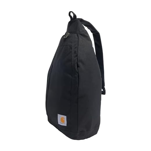


Stitch pattern: a 20–25 mm box with an X across it spreads load across the webbing; use 4–6 hand passes or set machine stitch length to 3–4 mm and sew slowly for straight, dense stitches. After sewing, trim the tail to 10–15 mm and briefly melt the cut end with a lighter, then press flat with pliers to stop fraying. Verify finish by applying a steady pull equal to the expected carry weight and check for slippage or stitch failure; redo sewing if any movement appears.
For wider webbing (38 mm / 1.5″) increase overlap to 50–60 mm and use matching hardware; leather or tubular types require specialized needles and slower feed rates. Select stainless steel or UV‑resistant acetal buckles for longevity in wet or sunny conditions.
Identify hardware: buckles, ladder locks, anchor points
Perform a 50 kg (110 lb / ~490 N) pull-and-hold test on each buckle and ladder lock; any slippage, deformation, cracking or permanent set means replace the component before reuse.
Visual and functional checklist
- Buckles (side-release, snap): inspect for hairline fractures, UV whitening, loose hinge pins, and damaged prongs; operate clasp 10–15 cycles to confirm positive engagement with no rattling.
- Ladder locks / tri-glides: check for sharp edges or burrs that cut webbing; verify the webbing remains locked under the 50 kg test with no micro-slip.
- Cam/quick-release buckles: examine cam teeth for wear and spring tension; cam should close fully and hold webbing under load without jump.
- Metal fittings (D-rings, carabiner anchors): look for corrosion, cracks, elongation, and heat discoloration; shake-test welded joints for looseness.
- Sewn anchor points: confirm box- or bartack-style stitching intact; loose ends, missing passes, or fraying within 1 cm of the seam require re-sewing or reinforcement.
Specifications and replacement guidance
- Match webbing width to hardware opening exactly (common widths: 10 mm, 15 mm, 20 mm, 25 mm, 38 mm); a mismatch >2 mm reduces holding strength and causes wear.
- Choose material by load: polymer acetal/nylon buckles suit light to medium duty; stainless steel or anodized aluminum fittings for high loads or marine exposure.
- Sewing: use polyester or bonded nylon filament for longevity; stitch pattern: box + X or multi-pass bartack with minimum 6 passes at high-load anchor points.
- Replacement parts: order components with specified opening width and inner thickness compatibility; verify manufacturer rated load when available.
Quick tools and actions: seam ripper, heavy-duty sewing machine or industrial needle, rivets and setter, lighter or heat-sealer for webbing ends, 10 mm Allen/Phillips for detachable buckles, and a 50 kg test weight or calibrated spring scale.
- Remove worn part, measure webbing width and thickness, and note stitch pattern.
- Select replacement with identical opening and stronger material where needed.
- Reinstall using box + X stitch or reinforced bartack; finish webbing ends with heat sealing or binding tape.
- Repeat the 50 kg hold test and perform 10 open/close cycles on moving parts.
For load transfer or vehicle-mounted carriage comparisons refer to best luggage rack for suv for hardware choices compatible with heavier cargo systems.
Choose matching webbing width and required tools
Match webbing width to the hardware’s inner slot size within ±1–2 mm; if a buckle or slider lists 25 mm use 25 mm (1″) webbing – common nominal widths: 10 mm (3/8″), 12 mm (1/2″), 19 mm (3/4″), 25 mm (1″), 32 mm (1.25″), 38 mm (1.5″), 50 mm (2″).
Selecting the webbing
- Measure the hardware slot with calipers; choose webbing equal to the measured slot or up to 1–2 mm narrower to allow smooth movement.
- Material choices: polyester – low stretch and UV resistant; nylon – higher abrasion resistance and slightly more stretch; polypropylene – lightweight and water-resistant but lower heat tolerance.
- Check manufacturer tensile rating if load-bearing: replace with webbing rated at least as high as original component or clearly marked with breaking strength.
- For sewn loops or anchor points use folded webbing width matching the stitch pattern: e.g., a 25 mm outer loop usually uses a 25 mm webbing doubled to 12.5 mm thickness; verify clearance in casing or channel before cutting.
Tools and precise use
- Seam ripper: cut only thread, not webbing–insert tip under a single stitch, lift and pull the cut thread out. Work incrementally along the seam; keep removed threads to prevent snagging.
- Sharp scissors or rotary cutter: make a square, fast cut across the webbing to avoid frayed edges; support the webbing on a hard surface for a clean edge.
- Lighter or hot knife: for thermoplastic webbings (polypropylene/polyester) briefly pass flame 1–3 seconds to fuse the edge; for nylon prefer a soldering iron/hot knife for cleaner finish. Hold flame perpendicular, do not char–test on a scrap piece first and work in ventilation.
- Pliers: use needle-nose or locking pliers to grip webbing when pulling through tight slots; use smooth-jawed pliers or wrap webbing with tape to avoid deformation.
- Feeding aids: fold 6–10 mm of tape over the end to stiffen for insertion, or attach a safety pin/awl to guide through channels and keep the braid from catching.
- Finishing: press melted edge flat with pliers or metal block while warm; optional heat-shrink tubing gives a neat capped finish – slide tubing over end and apply gentle heat.
- Safety: work in a ventilated area, wear heat-resistant gloves when using hot tools, and keep a damp cloth nearby for small burns.
For unrelated gear trends read are dslr cameras being phased out.
Detach Old Band and Mark Webbing Orientation and Stitch Locations
Remove original stitches with a seam ripper, cutting only the stitch lines and keeping the fabric and webbing intact; retain at least 5–10 mm of old stitch tails as a template for placement.
Detach procedure
1) Release stitches along attachment points, working from the outermost row inward; use fine micro-snips to trim cross-stitches and a needle-nose to tease out remaining fibres. 2) Keep each hardware piece in its mounting hole or lay it beside the opening in the same rotation to document orientation. 3) Mark the face that sat outward with a permanent marker (“O”) and the inward face with “I”. 4) If the webbing end was folded over a bar, measure the original feed length from the folded edge to the stitch line and record to the nearest millimetre.
Marking and measurement technique
Use tailor’s chalk or a fine-tip permanent marker and a steel ruler to transfer dimensions from the old attachment to the new webbing: measure back from the webbing edge the recorded feed length and draw a straight line; then mark stitch lines 3–4 mm from each long edge. At the intended sew area, place small punch dots or tiny awl holes at the four box corners to align during sewing. Label the box corners A,B,C,D to preserve stitch order when sewing.
| Webbing width (mm) | Recommended overlap/feed (mm) | Edge clearance for stitch lines (mm) | Stitch pattern & machine settings |
|---|---|---|---|
| 20 (¾”) | 30–35 | 3–4 | Box with X; stitch length 3–3.5 mm; use bonded polyester filament, needle 90/14 |
| 25 (1″) | 35–40 | 3–4 | Box with X; stitch length 3–4 mm; bonded polyester filament, needle 90/14–100/16 |
| 38 (1½”) | 45–55 | 3–4 | Large box with X; stitch length 3.5–4 mm; bonded polyester filament, needle 100/16 |
Record these four data points for each attachment: webbing width, feed length (mm), face marking (O/I), and stitch corner coordinates. Preserve one dismantled end as a physical template for machine setup and final verification.
Routing webbing through buckle and adjuster in correct sequence
Pass the webbing under the adjuster (from the underside toward the top), then through the buckle’s main bar toward the load-bearing side, and finally double back over the adjuster so the free tail runs parallel to the standing limb – this double-back arrangement maximizes friction and minimizes slip for load-bearing connections.
Exact routing steps: 1) Insert the free end under the lower throat of the adjuster so the loaded leg will seat on the upper bar. 2) Feed that end through the buckle’s center bar from the rear toward the front, ensuring the buckle’s fixed bar faces the direction of pull. 3) Bring the free end back over the center bar and through the opposite slot of the adjuster, forming two contact passes across the adjuster bar. Keep the webbing flat and un-twisted; print/face outwards for cosmetic alignment.
Target tail lengths and material finishes: for 25 mm (1 in) webbing, leave 30–50 mm (1.2–2 in) of tail inside the adjuster; for 38 mm (1.5 in) webbing leave 50–75 mm (2–3 in). If the end will be sewn into a permanent anchor, allow 60–80 mm (2.5–3 in) beyond the last hardware so a 20×20 mm box-and-X stitch fits cleanly. Melt synthetic ends briefly with a lighter and press flat; for natural fibres fold and topstitch or use a metal clinch/rivet 8–10 mm from the edge (two rivets spaced 20–25 mm apart for heavy loads).
Verification and tensioning: pull the standing limb hard while holding the buckle to seat the webbing against the bars, then apply a static test equal to twice the expected working load (for daypacks, test with 50–100 lb/22–45 kg). Any measurable slip over 5 mm indicates incorrect routing or insufficient tail; increase overlap or add another pass. For visual reference and a non-related diversion, see best donald trump umbrella gifs.
Secure the webbing end: sew, melt, or install an end cap to stop fraying
Best permanent finish: sew a 25 mm (1″) box with a diagonal X across it using bonded polyester or nylon yarn. Use a 3 mm stitch length, heavy-duty needle (machine 90/14 or 100/16), and 4–6 passes of the sewing head; hand-sewn option: use a size 3–4 leather needle and double-filament cord, backstitching each side. Apply a drop of clear seam sealant on the outside of the sewn area to lock filaments.
Fast, no-sew finish: fuse the cut edge with heat. Identify material first: polypropylene melts ~160–170°C, nylon melts ~220–250°C. Use a soldering iron set to temperature (200°C for polypropylene, 260°C for nylon) for controlled melts; with a lighter, apply brief, even passes (1–3 seconds) until edges bead and fuse. Immediately flatten the bead against a metal plate or flat pliers while hot to create a smooth edge. Work on a non-flammable surface, ventilate, and wear heat-resistant gloves.
Mechanical end caps: heat-shrink tubing: choose adhesive-lined tubing with a 3:1 shrink ratio sized for the webbing width (common widths: 19 mm, 25 mm, 38 mm). Cut 10–25 mm length, center over the tip (folded or single layer), apply heat evenly until adhesive flows and tubing hugs the webbing. Crimp caps: select brass/stainless steel crimp-on caps sized to width, insert folded end, crimp uniformly with flat-jaw pliers or a bench vise, then lightly peen edges to avoid sharp points. Plastic snap-fit caps are suitable for light-duty loads only.
Quality check and loads: after finishing, perform a pull test of 50–100 lbf (≈220–440 N) for 10 seconds while inspecting for slippage, deformation, or melt cracking. For sewn finishes recheck stitches after 24 hours; for heat-fused edges, sand lightly to remove hard burrs. Replace the finish if any failure or loosening appears during use.
Test adjustability and load-hold; trim and finish excess webbing
Load-hold and adjustability testing
Perform a static hold at 1.5× the maximum intended carried weight for 10 minutes (example: intended load 20 kg → test at 30 kg). Observe for permanent slip: acceptable movement is ≤10 mm for 25 mm (1″) webbing, ≤6 mm for 20 mm webbing under the test load.
Follow the static hold with a cyclic durability check: 200 cycles between 10% and 100% of intended load at roughly 6–10 cycles per minute. After 50, 100 and 200 cycles, tighten the adjuster to preset length and measure any cumulative creep; acceptable total creep ≤15 mm for 25 mm webbing over 200 cycles.
Conduct wet and dry tests: repeat the static hold and 50-cycle subset with the webbing soaked in fresh water (immerse 5 minutes, drain) and again when dry. Record difference in slip; if wet slip > dry slip by more than 50%, change adjuster or add a friction keeper.
Quick-field check: hang a calibrated spring scale from the attachment point, set desired length, pull downward with 50–100 N and confirm the adjuster does not move more than 5–10 mm. If it slides more, re-route webbing through hardware or replace the adjuster.
Trim and finish excess webbing tail
Leave a nominal tail length of 60 mm (2.4 in) beyond the final keeper for normal use; if space is tight use 40–50 mm but never less than 30 mm. Mark cut line perpendicular to weave with a fine-tip marker.
Cut with a hot-knife or sharp shears for a clean edge. For hot-knife use 200–300°C and a single smooth pass; for hand-cutting use a new razor and then seal edge with a soldering iron or lighter.
To melt-seal with a soldering iron: set tip to ~350°C, touch the webbing edge for 1–2 seconds until fibres fuse, then immediately press flat with smooth pliers or a wooden block to form a tidy bead. Avoid prolonged heating (more than 3 seconds) to prevent embrittlement or discoloration.
For lighter finishing (no hot-iron): hold flame 15–20 mm from edge, expose for 1–2 seconds while rotating the tail to heat evenly, then press against a metal flat tool to flatten the bead. Test one scrap piece first to dial timing.
Install end caps when extra abrasion resistance or a finished look is required: choose cap width matching webbing (e.g., 25 mm cap for 25 mm webbing) and a cap length 10–15 mm. Crimp with hand crimpers or a bench vise using a 2–3 mm incremental squeeze until cap grips uniformly; trim any protruding fibres and re-check adjuster fit.
If folding and sewing the tail back: fold 40–60 mm and sew a box-X pattern using bonded polyester thread (e.g., Tex 40 or size #69 commercial). Stitch length 3–4 mm, 6–8 passes across the box, and run a bartack at both ends for extra security.