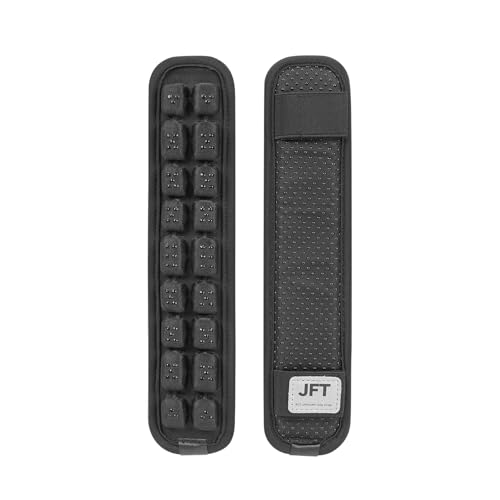

Replace shoulder straps with 50 mm nylon webbing and closed-cell foam pads of 10–15 mm thickness; sew anchors with triple-row stitching at 3.5–4.0 mm stitch length using bonded nylon or polyester thread (size 69 or 92). Position strap attachment points 120–140 mm apart along the pack’s upper spine to align with typical adult shoulder spacing; use box‑X and bartack reinforcements at all load-bearing junctions.
Install a load-bearing hip belt of 40–60 mm webbing with EVA or dual-density foam 15–25 mm thick; contour belt length so the centre sits over the iliac crest. Use 38–50 mm side-release buckles from reputable suppliers (ITW Nexus or Duraflex) rated above 1,000 N, and attach with a minimum 25 mm overlap of webbing, secured by box stitching plus bartacks at 10–15 mm intervals.
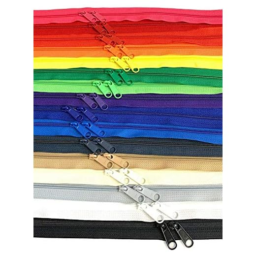
Swap critical hardware and closures for YKK VISLON zippers: use #10 for main openings and #5 for pockets. Reinforce zipper tape with an extra 12–15 mm fabric placket and double topstitch 3 mm from the edge. Add water resistance with a fluorocarbon-free DWR spray and interior seam tape; for stress points use a small patch of 1000D Cordura and Secure with Seam Grip or equivalent urethane adhesive.
Add a support sheet or stays sized to 60–80% of the measured torso (C7 to iliac crest). Choose materials by expected load: 3 mm HDPE for light loads, 4–6 mm aluminum or composite stays for heavier loads. Bond stays into a channel with 8–12 mm of closed-cell foam for shock isolation and stitch the channel with 3.5–4.0 mm stitch length, reinforcing both ends with bartacks every 5–8 mm.
Recommended workflow and tools: remove worn components; reinforce anchor points; fit new internal support; attach hip belt and shoulder straps; replace closures last to maintain shape. Use a heavy-duty walking-foot sewing machine or industrial machine capable of passing 3–4 mm needles, size 16–22 household needles for lighter repairs, rotary cutter, leather/nylon punch, rivet setter, and a tension-tested sewing thread. Keep Tenacious Tape, seam sealer, spare webbing in 25/38/50 mm widths, and spare buckles on hand for field repairs.
Practical modifications for a technical pack
Replace factory shoulder straps with 38–55 mm contoured straps built from closed-cell EVA foam (60 kg/m³), covered in 200D Cordura, sewn with bonded #92 nylon thread and secured with 20 mm bar-tacks at high-stress junctions to reduce pressure points by ~25% under a 20 kg load.
Swap main zippers for YKK Aquaguard #5 or YKK #10 coil (use #10 for frequent heavy use); expect a 3–5× longer service life versus generic sliders. Install a 3–5 mm polyethylene internal frame sheet or a 6 mm 6061-T6 aluminum stay for packs carrying 10–25 kg to increase torso stiffness without adding more than 120–220 g.
Add a structured hip belt: 40–60 mm closed-cell foam with 3–4 cm PE insert, 15–20 cm of load-transferring pad contact each side; aim to transfer 60–70% of carried mass from shoulders to hips. Place sternum strap 130–160 mm below shoulder seam with 10–12 cm adjustable range.
Materials and specifications
Recommended components and targets: 200D/500D Cordura for body panels; YKK zippers; ITW Nexus tri-glide buckles; 25–50 mm webbing (mil-spec 1,200 N breaking strength); lamination: 420D TPU for waterproofing; seam tape: 10 mm silicone-coated polyester.
| Component | Recommended spec | Expected outcome |
|---|---|---|
| Shoulder straps | 38–55 mm, EVA 60 kg/m³, 200D outer | Reduced shoulder fatigue; improved load distribution |
| Hip belt | 40–60 mm foam, 3–4 cm PE insert | 60–70% load transfer to hips |
| Frame | PE sheet 3–5 mm or 6 mm aluminum stay | Spine support without excessive weight |
| Zippers | YKK #5 Aquaguard or YKK #10 coil | Higher durability and smoother operation |
| Waterproofing | 420D TPU laminate + 10 mm seam tape | Water resistance for heavy precipitation |
Installation checklist
1. Remove original straps and inspect stitching paths; mark new stitch lines 8–12 mm from edge.
2. Reinforce attachment points with 60×40 mm nylon patches and two 6 mm rivets per side where load concentrates.
3. Sew new straps with a walking-foot sewing machine using 4–6 mm stitching length; finish with 20 mm bar-tacks at ends.
4. Replace zipper sliders; test full-range operation 20 cycles; apply silicone lubricant sparingly.
5. Insert frame sheet into dedicated sleeve; confirm torso curvature match–trim in 5 mm increments if needed.
6. Apply seam tape with a low-temperature heat press or iron at manufacturer-recommended settings; allow 24 hours curing.
Maintenance: wash with low-detergent cleaner (e.g., Nikwax Tech Wash), re-treat with spray-on DWR or TX.Direct after three wet-season uses, inspect thread tension and bar-tacks every 6 months, replace cordlocks that show >30% slippage.
Selecting compatible modular pockets and attachment points
Pick pouches that match PALS/MOLLE 25 mm (1″) webbing spacing and list male strap lengths long enough for at least three full weaves through the host grid (recommended strap length ≥ 60 mm when threaded).
Attachment standards and measurements
Verify PALS/MOLLE pitch: 25 mm horizontal webbing with 25 mm vertical row spacing. For laser-cut panels check hole pattern pitch – most vendors use 10 mm or 12.5 mm slot spacing; pockets made for 25 mm webbing will not reliably lock to 10 mm systems unless adapter straps are used.
Measure module base dimensions: pocket width must be ≤ host panel usable width minus 10 mm clearance to prevent creasing. Depth and volume should be measured in litres or cm: small admin pouches 0.5–1 L, medium 1–3 L, rifle-mag pouches 0.7–1.2 L each; ensure center of mass of a fully loaded pocket falls within 20–30 mm of the mounting plane to avoid torque on attachment points.
Check male strap count and weave pattern: two straps for light items, three or four for medium/heavy modules. Straps should accept a 25 mm ladder lock or snap and have reinforced end stitching (bar-tack or box-X) over at least 12 mm.
Materials, load ratings and reinforcement
Choose module fabrics by expected abrasion and weight: 500D nylon/Cordura for everyday carry, 1000D for high-abrasion or load-bearing use. Webbing: 25 mm nylon/polyester with minimum tensile strength 1,500 lbf (6.7 kN) for load-bearing applications; for accessory-only pockets 400–800 lbf (1.8–3.6 kN) is acceptable.
Hardware: avoid relying on small plastic hooks for heavy loads. Use stainless steel or aluminum fittings rated by manufacturer; aim for hardware rated ≥2× the expected static load. If rating data is unavailable, prefer steel snap-hooks or locking carabiners for anything over 3 kg.
Sewing and reinforcement: main attachment seams should use bar-tacks or box-X patterns with heavy bonded nylon thread (tex 70–138 or size 69–92) and 6–12 stitches per 2.5 cm (approx. 6–12 SPI). Add a 1.5–3 mm internal backing (nylon webbing or 0.8–1.2 mm Thermoplastic) behind the mouth of the module to spread load and reduce seam failure.
Compatibility checklist before purchase: confirm webbing width and pitch, verify strap length and weave count, check material denier and stated tensile ratings, inspect stitch pattern at attachment points, and test-fit unloaded module to ensure flush seating and unobstructed buckle operation.
Reinforcing seams and stress points with webbing and stitch patterns
Use 38 mm (1.5″) or 50 mm (2″) webbing for primary load paths; anchor with a 100–150 mm (4–6″) overlap and stitch through a 1000D Cordura backer at least the full overlap length.
Select webbing material by stretch: polyester for low stretch and superior UV/wet performance, nylon for slightly higher elongation and abrasion resistance; for extreme weight savings specify Dyneema®-core webbing (check manufacturer compression limits).
Sew with bonded nylon or bonded polyester thread. Typical choices: Tex 70/#69 for general use at 8–10 SPI (stitches per inch); Tex 138/#138 for high-load points at 6–8 SPI. Maintain 3.0–4.0 mm stitch length on heavy materials; use a walking foot and industrial needle (size 100/16 or 110/18) for consistent penetration.
Primary stitch patterns: Box-X (square with diagonal X) for strap-to-body connections; double row parallel stitching 6–8 mm apart for edge reinforcement; and dense bar-tacks (6–12 mm length) at the strap ends and pivot points. For small items use triple straight stitches along the webbing run to prevent seam creep.
Distribute shear by staggering multiple stitch lines and using a cross-panel load spreader: cut a rectangular backer 20–30% longer than the webbing overlap, glue with contact cement, then sew a Box-X plus two parallel rows. For repeated cyclic loads increase overlap to 150–200 mm and add an internal stainless washer plate beneath the stitching where hardware passes through.
Where a single stitch line is unavoidable, add a zigzag catch-stitch 3–4 mm from the primary seam and lock every 6–8 mm with short reverse stitching to stop propagation of tear. For vertical webbing runs attach a mid-span bar-tack every 60–80 mm to reduce flutter and localized flex.
Use reinforced rivets or stainless steel grommets at hardpoints that combine with stitched webbing; place rivets 8–12 mm outside the stitched perimeter and limit spacing to 25–40 mm when used in series. Avoid placing rivets through load-bearing seams without a backing plate.
After sewing, apply a thin coat of flex-compatible seam sealant to exposed thread heads and test ten cycles of the intended load at 50% of design load; inspect for stitch migration and add secondary stitching if elongation exceeds 3 mm. For solvent removal or rinsing of adhesives consult external resources such as best additive for dog water for teeth.
Suspension retrofit: swapping foam, straps, and tensioning systems
Replace the stock backpanel with a laminated sandwich: 10mm open-cell memory foam (comfort layer), 20mm medium-density EVA at 140–180 kg/m³ (load distribution), and 5mm closed-cell PE sheet (moisture barrier and shape retention); glue with contact cement (3M Super 77 or equivalent) and stitch perimeter with bonded nylon thread.
Foam core and shaping
- Materials and thicknesses: use EVA (ethylene-vinyl acetate) 110–180 kg/m³ for the main layer, PU or open-cell memory foam 40–80 kg/m³ for contour, closed-cell PE 30–60 kg/m³ as outer shell. Total thickness 30–40 mm for day-use packs, 40–60 mm for multi-day loads.
- Ventilation and lumbar geometry: cut 8–12 mm vertical channels (3–5 channels, spaced 25–40 mm) through the EVA layer to increase airflow without compromising stiffness; add a 20–50 mm raised lumbar pad shaped to match the posterior iliac crest.
- Shaping methods: hot-knife or band-saw for straight cuts; electric carving knife for contours; trim with 80–120 grit foam-safe sanding block for final fit. Bond layers with spray contact cement applied to both surfaces, press with roller and allow 10–15 minutes tack-up time.
- Attachment to frame sheet: glue foam to a 1.5–2.5 mm HDPE or 2–3 mm laminated composite frame sheet, use rivets or nylon dome rivets every 40–60 mm along the perimeter, then sew perimeter to shell with 4–6 mm stitch length using bonded nylon thread (Tex 135–210).
Straps, anchor points and tensioning systems
- Webbing selection: 25 mm polyester webbing for compression straps (breaking strength 2–3 kN), 38–50 mm nylon or UHMWPE for shoulder and hip webbing (3.5–7 kN). For light rigs use 12–16 mm Dyneema-coated cord for lightweight tensioning lines (breaking 1.5–3 kN).
- Buckles and hardware: use aluminum anodized or glass-filled nylon ladderlocks for micro-adjustments; for primary load-bearing hip and sternum use steel or aluminum triglide/cam rated ≥3 kN. Avoid thin injection-molded buckles on hipbelt anchors.
- Anchor reinforcement: fit a 1–2 mm UHMWPE or 2–3 mm Delrin backing plate behind each heavy anchor point; stitch pattern: 20 mm box with an X (box-X) plus two vertical bar-tacks. Use 3–5 passes on high-stress points with bonded nylon thread.
- Tensioning systems: replace single stay with a split-stay using 6–8 mm spring steel rods or composite carbon-fiber stays (3–4 mm thickness) for torsional stiffness. For continuous adjustable tension use 1.2–1.6 mm stainless steel cable (7×7 braid) with a Dyneema sleeving and low-friction POM pulley; route cable with exit angle ≤30° to minimize wear.
- Sewing specifics: use walking foot or compound feed for heavy webbing; stitch length 3.5–4.5 mm, seam allowance 10–15 mm for strap anchors. Use rustproof bar tacks or box stitches with minimum 10 mm overlap onto shell fabric.
- Tools and consumables: seam ripper, heavy-duty sewing machine (capable of Tex 135), rivet setter, contact cement, foam cutting knife, backing plates, bonded nylon thread.
- Removal: carefully remove existing stitches and rivets, retain the original frame sheet as a template. Mark new anchor locations with chalk and transfer to backing plates.
- Install frame and foam: bond foam sandwich to frame sheet, clamp for 30–60 minutes, then mechanically fasten every 40–60 mm.
- Attach straps: route primary webbing through backing plates and buckles, stitch box-X and bar-tack, trim and heat-seal webbing ends.
- Set tension: preload stays/cable to a moderate tension, then conduct dynamic cycling–50 cycles from zero to design load–inspect for creep. Final static test at 150% expected working load for 1 hour; re-tighten if any elongation >3% is observed.
Quick checklist: foam densities and total thickness matched to intended load; backing plates under all heavy anchors; webbing rated at least 1.5× expected peak load; stainless cable with low-friction routing for continuous tensioning; stitch patterns box-X plus bar-tacks and final static/dynamic testing completed.
Integrating electronics: mounting power banks, routing cables, and waterproof ports
Install a dedicated rear sleeve for a 10,000–30,000 mAh power bank (≈37–111 Wh) secured with a 50 mm hook-and-loop strap and 3–5 mm closed-cell neoprene to limit movement and abrasion.
- Power-bank selection
- Day pack: 10,000–20,000 mAh (≈37–74 Wh). Phone/tablet charging, 18–30 W PD sufficient.
- Extended field use: 20,000–30,000 mAh (≈74–111 Wh). Good for multiple devices; keep ≤100 Wh for airline carriage rules.
- If laptop charging is needed, choose USB-C PD rated 60 W or 100 W and use a certified e-marker 5 A cable for >60 W delivery.
- Mounting points and hardware
- Primary mount: rear-sheet sleeve against the pack’s frame sheet. Attach sleeve to frame sheet with bartack stitches every 30–40 mm along the edges.
- Retention: 50 mm wide hook-and-loop strap plus a 15–20 mm elastic keeper to stop vertical slippage.
- Shock isolation: add a 3–5 mm neoprene pad under the battery and 5–8 mm EVA foam riser to prevent direct contact with hard frame components.
- Hard-panel installations (panel-mount ports): reinforce cutout with 2–3 mm polycarbonate backing plate riveted with M3 rivets at 30–40 mm centers.
- Cable routing strategy
- Prioritize shortest practical run to device ports: 150–300 mm internal runs for shoulder-strap charging, 800–1,000 mm for external device pockets.
- Separate low-voltage power lines from antenna or audio runs by ≥20 mm to reduce interference.
- Use a dedicated internal conduit (30–40 mm wide sewn channel) from battery sleeve to shoulder strap; include a 10–15 mm inspection window (snap or Velcro) at midpoint for maintenance.
- Anchor cable at three points: at battery exit, mid-run clip, and at port–use 10–12 mm adhesive cable clips or 20 mm webbing loops to prevent sagging and chafing.
- Cable and connector specs
- Phone/tablet: USB-C PD 18–30 W, use 28–24 AWG power conductors. For PD >60 W use e-marker 5 A cable (AWG 20–22 power conductors).
- Data lines: shielded twisted pair for USB 2.0/3.0 paths; keep data runs ≤500 mm from internal hub to external port to reduce signal loss.
- Choose right-angle connectors inside shoulder straps to avoid sharp bends; maintain bend radius ≥8 mm for high-current cables.
- Add a ferrite bead or inline common-mode choke where cable runs cross RF-sensitive equipment.
- Waterproof port selection and installation
- Preferred rating: IP67 or IP68 panel-mount ports with integrated silicone gasket for USB-C or USB-A. IP67 = immersion to 1 m for 30 min.
- Common mounting details: USB-C bulkhead typical hole ≈12–13 mm diameter (verify manufacturer datasheet); secure with M3 machine screws or snap-in flange per part spec.
- Use a 1–2 mm silicone gasket compressed against the backing plate; compressive clearance should be 0.5–1.0 mm to maintain seal without over-stressing plastic.
- Cable gland for internal-to-external pass-through: select PG7/metric M10 equivalent for single cable diameters 5–8 mm; tighten nut to compress nitrile rubber insert for sealing.
- For multiple cables, use a molded multi-port USB bulkhead with integrated O-ring and replaceable gasket rather than multiple glands to reduce leak paths.
- Strain relief, sealing and serviceability
- Combine mechanical clamp + silicone potting only for permanent installs; prefer removable cable glands and heat-shrink strain reliefs for field service.
- Use 20–30 mm of adhesive-lined heat-shrink over solder joints and include an inline molded strain-relief sleeve to prevent axial stress on connectors.
- Seal exterior seams near port with a thin bead (1–2 mm) of neutral-cure silicone; allow full cure 24 hours before water exposure.
- Electrical protection and testing
- Install a resettable polyfuse inline sized at 1.25× expected maximum current. Example: for 60 W at 20 V (≈3 A) use a 4 A polyfuse; for 100 W (≈5 A) use a 6–7 A polyfuse.
- Use surge-protected PD controllers or certified power banks with overcurrent, overtemperature and short-circuit protection built in.
- Test procedure: run full-load charge for 30 minutes and record surface temperature rise; aim for <10 °C above ambient on battery enclosure and <20 °C on plastic port surrounds.
- Waterproof test: after installation, perform 1 m submersion (IP67) for 30 minutes or spray test per IPX5 procedures depending on chosen rating.
- Maintenance checklist (periodic)
- Monthly: inspect gaskets, verify fastening torque on portal screws, check cable anchors for wear.
- Every 6 months: run a full-load charge cycle, confirm polyfuse reset behavior, replace any cables with frayed insulation.
- Replace silicone gaskets every 12–18 months in heavy-use or saltwater environments.
FAQ:
What materials and hardware should I choose when upgrading a high-end backpack to withstand heavy use and weather?
First, assess the bag’s intended use: backpacking, urban carry, or technical climbing. For fabric, choose abrasion-resistant textiles such as Cordura (500–1000D) for heavy wear zones, and lighter laminated nylon or Dyneema composite for panels where weight and water resistance matter. Reinforce high-stress patches with Hypalon or leather. Use coil or reverse coil YKK zippers for water resistance and smooth operation; add zipper garages or storm flaps where exposure is likely. For webbing and straps, pick 25–50 mm nylon or polyester with high tensile strength and UV resistance. Replace small plastic buckles with metal or high-grade Acetal where longevity is required; magnetic closures (Fidlock) can be convenient for pockets but test for field reliability. For structural support, swap out flat stays for aluminum or carbon fiber rods in the spine or side channels if you need lighter, stiffer support. Finish seams with PU seam tape and apply a durable water-repellent (DWR) treatment to outer fabric. Use bonded nylon or polyester thread (Tex 70–210) and bar-tack critical points; if sewing by hand, waxed thread plus reinforced stitching will hold. Typical cost ranges: materials and hardware for a partial upgrade often run $30–150; structural swaps or professional reworks may reach $150–350, depending on parts and labor.
How can I add an internal hydration sleeve and tidy cable routing for electronics without compromising pack volume?
Plan the layout before cutting. Choose a thin, semi-rigid hydration sleeve sized for your reservoir; attach it to the rear panel with low-profile Velcro or sewn channels positioned so the reservoir rests against the internal frame sheet. Add a hose exit port at the top corner using a reinforced grommet and a small elastic loop on the shoulder strap to clip the bite valve. For electronic cables, install a narrow zippered pocket near the top of the main compartment with a small pass-through grommet for a charging cable. Use flat cable channels or strips of Lycra along the shoulder strap interior to keep wires flush and flexible. Keep these additions close to the pack’s back to avoid stealing volume from the main load space. Seal grommets and seams around ports with flexible silicone or seam sealant to ward off moisture. If you are unsure about modifying the fabric, consider adding a removable sleeve that slots into place rather than altering the pack body.
Which alterations improve load stability and reduce fatigue on multi-day treks, and how should I implement them safely?
Focus on distributing weight to the hips, stabilizing the load, and tailoring suspension to your torso. Replace or upgrade the hip belt with thicker foam and a shaped, articulated belt that transfers load to the ilium; use closed-cell foam or molded EVA for comfort and durability. Add or adjust load-lifter straps (placed just above the shoulder straps) to pull the top of the pack closer to your shoulders, which prevents the pack from pulling you backward. Consider inserting contoured foam pads or a replaceable frame sheet to maintain a small gap between the pack and your spine for ventilation while keeping vertical stiffness. If the pack lacks internal divider(s), install removable compression straps inside to bind contents near the pack’s center of gravity. For heavy loads, switch to stronger shoulder straps with additional foam and a sternum strap placed to allow natural breathing; a sliding sternum buckle allows minor adjustments on the trail. Always match frame length to your torso measurement; too long or too short a frame causes imbalance and pain. When cutting or sewing, reinforce all attachment points with box stitches and bartacks; if you lack heavy-duty sewing equipment, use professional repair shops for structural changes. After modifications, load the pack progressively and test with full weight on short outings to fine-tune strap tension and belt placement before committing to longer trips.

