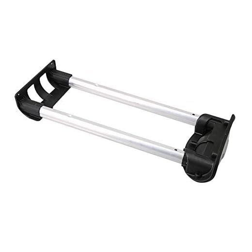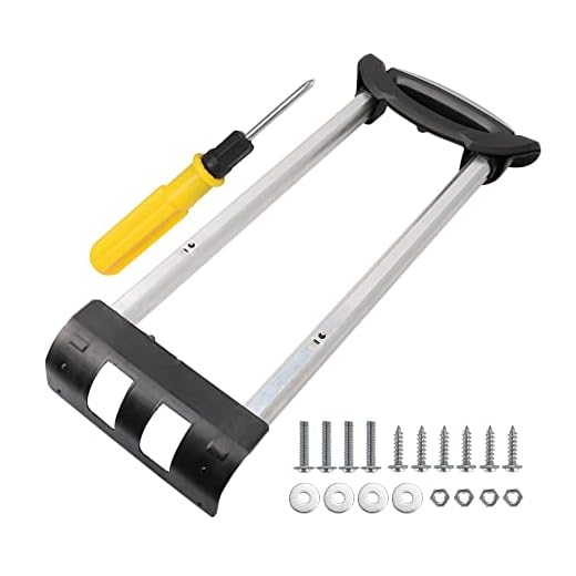
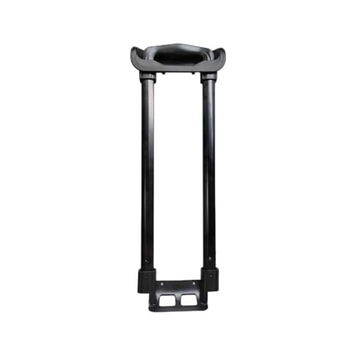

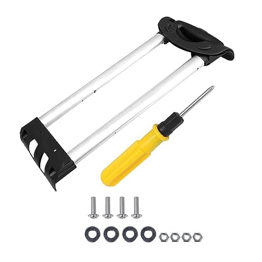
Recommendation: choose a three-stage telescopic pull-bar made from anodized aluminium with tube diameters ≥14 mm and a nominal extension of 40–50 cm; prefer dual-rail assemblies for lateral stability and avoid hanging more than 5 kg from the grip to prevent premature wear.
Typical construction uses an outer sleeve, one or two inner concentric tubes and a push-button release that engages a series of spring-loaded detents. Sections are usually 12–16 mm (inner) to 16–20 mm (outer) in diameter; detent spacing commonly ranges from 12 to 20 mm. Locking is achieved when a steel pin or molded nylon ball snaps into a notch machined or formed on the inner tube; a compression spring behind the button provides return force of roughly 3–8 N depending on design.
Materials affect behaviour: anodized aluminium offers a good strength-to-weight ratio and resists galling, stainless steel increases rigidity (+200–400 g on average for a full assembly) but adds mass, while inexpensive alloys and thin-wall tubing produce more play. Bearings or sintered-bronze bushings at contact points reduce transverse wobble; low-cost designs use molded polymer bushings that wear faster under grit.
Maintenance and quick fixes: clean grit from the tubes with compressed air, wipe surfaces with isopropyl alcohol, apply a light silicone spray to sliding faces (one short spray per rail), and cycle the bar 10–15 times to work lubricant in. Tighten fasteners and inspect rivets; if extension stutters, check detent-notches for burrs and smooth with a fine file. For persistent lateral movement, add thin shim washers at the base or replace polymer bushings with metal-backed versions. Replace the push-button spring if travel exceeds 10 mm or return force drops noticeably.
Selecting the right telescoping tube: materials and wall thickness for strength
Recommendation: For carry-on sized cases choose 7075-T6 outer tubes with 1.2–1.6 mm wall and 6061-T6 inner tubes at 0.9–1.2 mm; for checked-bag duty specify outer walls 2.0–2.5 mm or swap to 17-4PH stainless (heat-treated) with 1.2–1.8 mm wall, or a continuous-fiber carbon composite tube ≥1.5 mm equivalent.
Material properties (typical values): 6061-T6 Al – density 2.70 g/cm³, yield ~275 MPa, E ≈69 GPa. 7075-T6 Al – density 2.81 g/cm³, yield ~500 MPa, E ≈71 GPa. 17‑4PH stainless – density ~7.8 g/cm³, yield range 600–1,100 MPa depending on temper, E ≈200 GPa. CFRP – density 1.5–1.8 g/cm³, tensile strength 600–1,500 MPa, design modulus 70–200 GPa depending on layup.
Wall-thickness guidelines by application and tube diameter: Outer-stage circular/oval tubes: 20–28 mm OD – 1.2–1.6 mm for light duty, 1.6–2.2 mm for normal use, 2.2–2.8 mm for heavy loads. Inner-stage tubes (nested): subtract 0.2–0.4 mm from the adjacent outer wall but do not go below 0.8 mm for aluminium (risk of denting). For multi-stage systems reduce inner-stage thickness progressively but maintain minimum cross-sectional stiffness.
Lateral stiffness and buckling check (practical): Use Euler buckling formula Pcr = π²·E·I/(K·L)² to verify axial stability for long unsupported lengths; for side-load bending compute σ = M·c/I. Example: a 25 mm OD Al tube with t=1.2 mm has I ≈7.4·10³ mm⁴; a 400 mm unsupported extension under a 50 N lateral force produces bending stress ~34 MPa, well under 6061-T6 yield. If calculated σ approaches 40–60% of yield, increase wall thickness or change material.
Clearance, tolerances and fit: Radial clearance per mating surface: 0.3–0.6 mm per side (0.6–1.2 mm total) balances smooth travel and minimal play. Roundness/ovality tolerance: <=0.05 mm. Edge radii at slots/holes: R≥1.0 mm to avoid stress concentrations. Surface finish: 0.8–1.6 µm Ra on sliding surfaces.
Wear resistance and corrosion: Hard anodize 15–25 µm on aluminium outer stages to reduce abrasion; add low-friction bushings (nylon, PTFE) at contact points. For humid or marine exposure prefer 6061 with anodize or stainless 17‑4PH; avoid dissimilar metals contacting bare CFRP without insulating barrier.
Manufacturing choices: Prefer seamless cold-drawn or precision-extruded tubes for consistent wall and minimal seam weak points; welded seam tubes require post-weld heat treatment and higher wall thickness to offset localized weakness. For CFRP use filament-wound or pultruded continuous fibers with internal smooth liner to preserve sliding clearances.
Practical selection checklist: outer-stage alloy and t, inner-stage t, radial clearance, finish/coating, bushing material, manufacturing method, verify with Euler/bending checks for intended unsupported extension and lateral load cases.
Release and lock designs: push-button, latch, and auto-lock mechanics
Recommendation: choose a push-button with dual-ball detent and a stainless-steel return spring (302/316), rated for ≥10,000 cycles and salt-spray resistance ≥48 hours for regular airline use.
Push-button (detent) systems
- Core principle: spring-loaded ball(s) engage a circumferential groove on the inner tube; button retracts balls to allow travel.
- Key dimensions: button travel 3–6 mm; detent ball diameter 3–4 mm; groove depth 0.6–1.2 mm; tolerance ±0.05 mm for reliable indexing.
- Spring specs: coil spring free length 12–18 mm, wire diameter 0.30–0.55 mm, initial compression force 12–25 N at installed height.
- Materials: detent balls hardened steel (HRC 58–62) or ceramic for corrosion resistance; button shaft and housing 304 stainless or zinc die-cast (premium preference: stainless).
- Performance markers: acceptable release force 15–35 N; positive index with ≤1 mm axial play when locked.
- Common failures: spring fatigue, groove wear, ball pitting from contamination; prevention: use sealed housings and periodic cleaning every 6 months or after ~500 cycles.
- Service tip: if button sticks, remove assembly, clean grease/dirt with isopropyl alcohol, replace spring if free length has shortened >10%.
Latch and auto-lock mechanisms
- Latch (lever) variants: cam or pawl engages a notch on inner tube; lever travel typically 10–20 mm with cam radius sized to produce 20–60 N holding force under axial load.
- Auto-lock (ratchet/pawl) variants: multi-position pawl drops into indexed teeth; recommended tooth pitch 3–5 mm, tooth height 0.8–1.5 mm for positive engagement.
- Material guidance: pawls and cams heat-treated steel (case hardness HRC 45–55); housings anodized aluminium or reinforced polymer for weight reduction; use stainless fasteners in humid environments.
- Release actuation: spring-return release lever with pre-load 8–20 N for deliberate operation without accidental trips; button-to-pawl linkages should use clevis pins with retaining clips, not press-fit rivets, to ease servicing.
- Safety and accidental retraction: include an over-center geometry or secondary lock that requires >30° motion to release to reduce unintentional collapse during handling.
- Durability testing: aim for 5,000 cycles minimum for economy, 10,000+ cycles for premium; perform 96-hour salt spray for seaside use; static axial load test 2–3× expected service loads (e.g., 200–300 N).
- Diagnostics: check pawl tooth wear visually (rounded edges reduce engagement depth); measure play–more than 2 mm axial free travel indicates imminent replacement.
Selection checklist for purchase or repair:
- Rated cycles ≥ required usage (5k/10k threshold).
- Corrosion-resistant materials for springs and balls (stainless/ceramic/hardened steel).
- Positive indexing with ≤1 mm play; release force 15–35 N for push-buttons, 20–60 N holding for latches.
- Serviceable fasteners and replaceable springs/pawls.
- Manufacturer data sheet with test protocols (cycle count, salt spray hours, static axial load).
Repair and maintenance quick rules:
- Clean mechanism quarterly with compressed air and isopropyl alcohol; lubricate sliding surfaces with light white lithium grease (thin film only on detent groove).
- Replace springs showing >10% reduction in free length or any corrosion pitting on balls/pawls.
- For aftermarket upgrades, swap zinc housings to stainless or reinforced polymer to reduce fracture risk during impact.
For product comparisons and recommendations that factor in locking assembly quality and overall build, see best luggage money can buy.
Internal rod assembly load transfer during pull
Design for a peak pull load of 3–5× expected user force; specify a minimum design load of 1,200 N for consumer-grade telescopic pull systems (typical single-user peak ≈200–400 N) and apply a safety factor of 3–5 for joints and fasteners.
Primary axial path: force enters through the grip bracket, transmits into the top tube, flows axially through nested tubes, and terminates at the base anchor or carriage. Use paired parallel tubes or a three-rod arrangement to split axial force; each rod should carry no more than 40–50% of the total design load to limit local stresses and reduce bending sensitivity.
Account for off-axis loads by combining axial and bending stresses: σ_total = F/A + M·c/I, with M = F·e (e = lateral offset). Example: F = 250 N, offset e = 10 mm, tube OD 12 mm, wall t = 1.2 mm → I ≈ 8.14·10^−10 m^4, c = 6 mm, gives bending stress ≈18 MPa and axial ≈5.5 MPa; total ≈24 MPa, well below 200 MPa yield of stainless steel. Maintain design margins by increasing wall thickness or adding a second tube if calculated σ_total approaches material yield / (chosen SF).
Buckling control for compressive loads uses Euler: Pcr = π^2·E·I/(K·L)^2. For a free-fixed assembly use K≈2; with the same tube and L = 0.5 m, Pcr ≈1,500 N, so keep unsupported length and slenderness ratio low or increase I for longer assemblies.
Connection details transfer shear and compression at pins, rivets and end fittings. Use pins ≥4 mm diameter in single shear; with conservative shear strength 200 MPa a 4 mm pin area (~1.26·10^−5 m^2) yields ≈2,500 N raw capacity. Design for multiple shear planes or larger pins when expected load >400 N per pin after SF.
Reduce stress concentrations and distribute contact pressure by: 1) using hardened steel end-fittings with radiused transitions, 2) adding thin polymer liners (PTFE or nylon, 0.5–1.0 mm) between sliding tube surfaces to increase bearing area, 3) chamfering tube edges to avoid edge-loading at carriage seats.
Fretting and wear mitigation: apply low-viscosity PTFE-based grease to sliding surfaces; specify surface finish Ra ≤0.8 µm for mating tube faces to avoid micro-notches. Consider thin anodize or conversion coating on aluminum tubes to increase surface hardness and reduce adhesive wear when paired with polymer liners.
Anti-rotation and load-sharing features: splines, flattened flats, or keyed interfaces transfer torsion and shear across a larger area than single-pin joints. A three-lug top carriage that clamps onto multiple tube faces equalizes load distribution and reduces peak bearing pressure; size clamping contact to keep contact stress <50 MPa with chosen polymer or metal contact material.
Testing targets: static pull to 2–3× design load without permanent set, 10,000 cycle push/pull with ≤0.5 mm play increase, and shear test of fasteners to ≥design load·SF. Document measured deflection, pin shear, and tube ovalization; iterate tube geometry or add intermediate supports if deflection compromises locking engagement.
Diagnosing and fixing a stuck telescoping rod: step-by-step troubleshooting
Apply a penetrating spray (Kroil, PB Blaster or WD‑40 Specialist) at the tube collars, press the release actuator and pull with a steady force of about 10–20 N (≈1–2 kgf); repeat cycles of spray + movement for 60–90 seconds before escalating.
Quick diagnostic checklist
1) Visual: extend as far as possible and inspect tube junctions for grit, bent sections, or foreign objects trapped in the guide collar.
2) Feel: with the actuator pressed, move the shaft slowly; if motion is rough and intermittent, suspect corrosion or debris; if it moves freely and then locks, suspect a broken detent or spring.
3) Sound: creaking/grinding → metal-on-metal abrasion; clunk then stop → broken internal stop or misaligned rivet/pin.
4) Obstruction test: run a thin flexible rod or strong air blast (6–8 bar max) down the outer tube to eject debris; do not exceed pressure that deforms plastic parts.
| Symptom | Probable cause | Immediate fix | Parts/tools |
|---|---|---|---|
| Completely immobile | Corrosion, packed grit, or seized rivet | Penetrating spray + repeat flexing; drill out rivet if seized | Penetrant, drill 3–4 mm, punch, rivet gun, safety glasses |
| Moves in/out but won’t lock | Broken detent spring or worn slider | Remove end cap, replace spring/slider, reassemble | Replacement spring (measure wire Ø and free length), small screwdriver set, pliers |
| Sticks at mid travel | Bent inner tube or misaligned guide | Straighten tube with soft-jaw vise or replace tube section | Soft jaws, calipers to check runout, spare tube section |
| Intermittent binding | Debris in guide collar or damaged plastic slider | Clean, lubricate with silicone spray, replace worn slider | Compressed air, silicone spray, replacement slider |
Disassembly and repair steps
1) Remove wheel housing/end cap: locate screws (usually Phillips #1/#2 or Torx T10/T15); keep fasteners organized on a magnetic tray.
2) Extract shaft assembly: once end cap is off, compress the actuator and slide the assembly out slowly; note orientation of detent and spring for reassembly.
3) Inspect inside tube: use a torch and inspection mirror; remove visible debris with a brass brush and 90° pick. Avoid steel that will score the tube.
4) Deal with a seized rivet: center‑drill the rivet head with a 2.5–3.5 mm bit, then punch the mandrel through; replace with a 3.2 mm pop rivet or M3 screw + nyloc nut where space allows.
5) Replace soft parts: measure slider thickness and spring dimensions before ordering; typical detent springs are stainless steel, wire Ø 0.6–0.9 mm, free length 10–18 mm depending on design.
6) Realign bent tubes: mark runout with calipers; if runout >0.5 mm over 100 mm, replace tube section. Minor bends can be corrected in a soft‑jaw vise using slow, incremental pressure.
7) Reassembly: apply a single light coat of silicone spray inside the tubes (avoid oil‑based lubricants on plastic sliders), reinsert shaft, verify smooth travel and reliable locking through 20 full cycles before reinstalling end caps.
8) Final test and tolerances: full extension should be parallel and not wobble more than 2–3 mm laterally; actuator travel typically 3–6 mm – confirm positive engagement at each locking position.
Preventive maintenance for longevity: cleaning, lubrication, and screw checks
Perform a maintenance cycle every 3 months or after three multi-day trips: fully extend the telescoping assembly, clear debris, apply a targeted lubricant, and verify fastener tightness.
Cleaning procedure (5–10 minutes): fully extend all sections; wipe inner and outer rails with a lint-free cloth soaked in 70–90% isopropyl alcohol to remove grease and salt; use a soft-bristled toothbrush for corners and end caps; blow out remaining dust with low-pressure compressed air (30–40 psi). For corrosion or sticky residue, repeat alcohol wipe and follow with a dry cloth until metal looks bright.
Lubrication: For metal-on-metal sliding surfaces use a PTFE spray (one short 1–2 second burst per section) then wipe excess – PTFE reduces stick-slip and attracts less dirt than oils. For plastic guides and pivots use a silicone spray labeled safe for plastics (1 short burst). For hinge/pivot pins and lock mechanisms apply 2–3 drops of light sewing-machine or general-purpose machine oil (viscosity similar to ISO VG 32). Avoid heavy greases on thin telescoping tubes unless specified by manufacturer; if metal surfaces show pitting, use a thin film of white lithium grease sparingly (pea-sized amount distributed with cloth).
Amount and frequency: one maintenance cycle: PTFE 1–2 bursts per tube, silicone 1 burst on polymer parts, oil 2–3 drops per pivot. Frequency: heavy use (weekly travel) – monthly; moderate use – every 3 months; storage or coastal exposure – rinse with fresh water and service after drying, then lubricate.
Fastener inspection and torque guidance: visually inspect mounting screws, rivets and bolts for movement, missing washers, or damaged threads. Typical tightening torques (steel fasteners): M3: 0.6–1.0 N·m; M4: 1.5–2.5 N·m; M5: 3.0–4.0 N·m. If no torque wrench available, tighten until snug then add no more than 1/8 turn. Use a medium-strength threadlocker (e.g., Loctite 243) on screws that loosen repeatedly; avoid threadlocker on plastic-embedded screws unless specified.
Replacement and corrosion control: replace stripped screws with stainless A2 or zinc-plated steel of identical thread pitch and length. For assemblies exposed to salt air, choose A4 stainless where available and coat visible metal with a thin corrosion inhibitor after cleaning. If plastic threads are stripped, replace the insert or use a helicoil-type repair where feasible; do not overtighten into plastic housings.
Quick troubleshooting tips: sticky extension – clean + PTFE; noisy pivot – 2–3 drops of light oil; persistent wobble – inspect screw torque and replace worn washers or bushings. Log each service date and observed issues to detect progressive wear before failure.
Label your case for faster identification after maintenance: use best luggage markers to mark service dates or owner contact information.
FAQ:
How does a telescoping luggage handle actually extend and lock in place?
Most retractable handles consist of two or three nested metal tubes that slide inside each other. A button on the grip releases an internal catch so the inner tube can move. When you pull the handle up, the alignment of grooves or notches lets a spring-loaded pin or latch drop into place in one of several positions; that latch prevents the tubes from sliding back down. To retract, you press the release button, which withdraws the latch, allowing the tubes to slide back together. Small bearings or low-friction inserts keep the movement smooth, and an internal spring often helps the tubes pop into their extended position. The housing at the suitcase top secures the whole assembly to the shell and transfers load to the mounting plate and rivets or screws.
Why does my luggage handle wobble and is that something I can fix at home?
A wobbly handle usually comes from wear or loosened fasteners inside the handle housing. Common causes are stripped plastic bushings, worn metal collars, loose mounting screws, or dirt and grit in the guide tubes. First, remove the suitcase lining near the handle to inspect the mounting plate and fasteners. Tighten any loose screws; if parts are riveted, those rivets can wear and may need replacement. Clean tube interiors and bearings with compressed air and a soft brush, then apply a dry silicone or PTFE spray to avoid attracting dust. If plastic bushings are cracked or missing, replacing them or wrapping thin Teflon tape around the tube where it rubs can reduce play. Bent or heavily worn tubes usually require a replacement handle assembly. Small home repairs can stop wobble in many cases, but for structural damage seek a repair shop or manufacturer parts.
Are there different styles of retractable handles and which types last longer?
Yes. Typical styles include two-tube and three-tube telescoping handles, single-post designs, and integrated frames with molded grips. Handles made from thicker-walled aluminum or stainless steel last longer than thin alloys or mostly plastic assemblies. Dual-tube designs offer better lateral stability than single-post types. Also check how the handle is attached: screwed or bolted mounts allow service, while riveted or molded mounts are harder to repair. Quality of the locking mechanism and internal bushings has a big effect on lifespan.
What routine maintenance will keep a retractable handle working smoothly for years?
Regular care is straightforward. Periodically open the handle fully and clear debris from the tubes with compressed air or a soft brush. Wipe external parts with a damp cloth, then dry. Apply a small amount of dry silicone or PTFE spray inside the tubes to reduce friction; avoid heavy oils that attract dirt. Check and tighten accessible screws on the mounting plate and handle head. Do not hang heavy loads from the handle—use external straps or the suitcase body for added weight. When packing, retract the handle carefully and avoid slamming the lid closed. If you notice grinding, binding, or misalignment, stop using the handle until you inspect it, since continued force can bend tubes or damage the locking latch. With periodic cleaning and light lubrication, many handles remain serviceable far longer than average.
Can I replace a broken retractable handle myself and what tools or parts will I need?
Yes, do-it-yourself replacement is possible if you can access the internal mounting area. Typical tools: screwdrivers (Phillips and flat), Torx bits if required, pliers, a rivet gun if the old handle is riveted, and replacement screws or rivets. Parts needed include a matching handle assembly or compatible replacement, and any bushings or mounting plates. Steps: open the interior lining to expose the handle mount, remove fasteners or drill out old rivets, lift out the damaged assembly, fit the new handle and secure it with screws or new rivets, then test operation before re-securing the lining. Take care with alignment so the tubes slide freely. If the shell or mounting point is cracked, professional repair or a manufacturer replacement is safer than a home fix.


