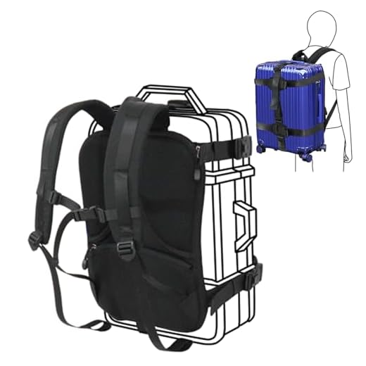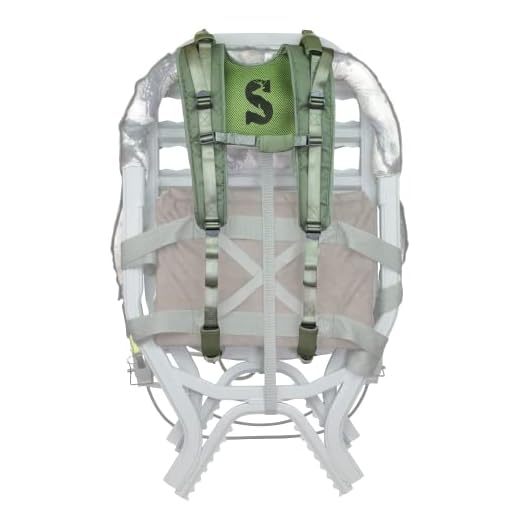


Use 25 mm (1″) 1000D nylon webbing combined with 6–8 mm closed-cell EVA foam and 25 mm ladder-lock buckles when replacing shoulder supports on a daypack; this combination balances durability, padding and adjustability.
Cut two pieces to 60–95 cm (24–38 in) based on torso measurement from the C7 vertebra to the top of the hip belt: common day-use lengths sit at 45–60 cm (18–24 in), extended torso setups 70–95 cm (28–38 in). Add 20–25 mm extra at each end for terminations and folding.
Overlap webbing ends 20–25 mm and secure with a box‑x stitch pattern using bonded polyester thread (Tex 70 or 40wt) and an 18/110 needle on a heavy‑duty machine; apply a minimum of five parallel rows at primary load points and a 15–20 mm wide bar‑tack reinforcement at the attachment. Glue foam to webbing with contact cement prior to topstitching to prevent shifting.
Heat‑seal raw webbing edges with a hot knife or soldering tool to stop fraying. Match hardware width to webbing width (25 mm hardware matched to 25 mm webbing, 38 mm hardware matched to 38 mm webbing); prefer metal or high‑strength acetal brands such as YKK or ITW Nexus. Verify finished assemblies by suspending 20–30 kg (44–66 lb) during 60 s and inspect stitching, hardware engagement and foam adhesion before regular use.
Select materials and webbing based on expected load
Choose webbing whose minimum breaking strength ≥ (maximum carried mass in kg × 9.8 N/kg) × safety factor – use safety factor 4 for everyday packs, 6 for heavy loads, 8–10 for suspended or life-critical loads.
Load categories and specific recommendations
Light load (≤10 kg): 25 mm (1″) flat polyester or nylon webbing, minimum breaking strength ≥2 kN. Use 12–25 mm chest/sling webbing rated ≥1 kN.
Medium load (10–25 kg): 25–38 mm (1–1.5″) tubular or flat nylon/polyester, minimum breaking strength ≥4 kN. Shoulder harness width 25–38 mm; use 38 mm for wider contact and comfort.
Heavy load (25–45 kg): 38–50 mm (1.5–2″) nylon or polyester laminate; consider UHMWPE (Dyneema®) overlays for high strength-to-weight but back up with sewn polyester covers. Minimum breaking strength ≥8 kN; use 40–50 mm hip/waist webbing rated to the same kN.
Very heavy / suspended loads (>45 kg): 50 mm+ mil‑spec tubular nylon or bonded UHMWPE webbing, minimum breaking strength ≥12–20 kN; use metal hardware rated to equal or higher strength.
Materials, attachment technique and hardware
Nylon: higher dynamic elongation, good abrasion resistance; choose when some stretch helps shock absorption. Polyester: lower stretch, better UV and wet stability – preferred when low elongation under load is desired. UHMWPE: extremely high strength and low stretch; do not rely on sewn terminations alone – use mechanical clamps, welded splices, or encapsulation with sewn polyester sleeves.
Sewing: fold webbing 20–30 mm before stitching; use box-x pattern with a minimum of 10–14 stitches across the box and two parallel box-x rows for medium loads. Stitch length 3–4 mm with bonded nylon or polyester thread. Add bartacks (8–12 passes) at high-stress endpoints. For heavy and very heavy categories, use multiple parallel box-x rows or add rivets/metal crimps to share load.
Hardware: match buckle/tri‑glide/ladder-lock rated at or above webbing kN rating. For loads above 8 kN avoid acetal plastics; specify anodized aluminum or stainless steel. Use rounded edges on metal fittings to prevent webbing abrasion; add abrasion patches where webbing crosses sharp seams.
End treatment and inspection: heat-seal synthetic ends with a 3–5 mm melted bead, then fold and sew. Inspect stitching and hardware for 10% stretch, fraying, or corrosion before every extended trip; replace any webbing losing more than 15% of rated integrity or showing concentrated wear.
Measure and cut harness length to torso height with adjustment range
Set each shoulder harness length to measured torso (C7 to iliac crest) + 25–35 cm to allow full adjustment; cut main webbing to that single-side length and add 4 cm per sewn termination.
Measure torso with wearer upright: find C7 (most prominent cervical spinous process) and the highest point of the iliac crest, record distance in centimetres. Use that value as the base measurement.
Quick reference cutting lengths
Child (34–38 cm torso): cut single-side webbing 60–73 cm. Small (38–43 cm): 63–78 cm. Medium (43–48 cm): 68–83 cm. Large (48–53 cm): 73–88 cm. XL (53–58 cm): 78–93 cm. Adjust numbers +/- 5 cm to match personal preference.
If using a continuous loop design, multiply single-side length by two and add 8–12 cm total for seams and anchor routing. If one end is fixed and the other uses a ladder-lock or tri-glide, leave a free tail of 20–30 cm beyond the adjuster to permit easy tightening and tucking.
Hardware and finishing allowances
Add an extra 5–10 cm per side when routing webbing through triple-bar sliders, buckles, or foam pockets to prevent binding. Add 2 cm per folded end for stitching; heat-seal cut webbing edges, then stitch a 10 mm-wide bartack or box stitch over the folded area.
Design target adjustment range should cover about ±12–18 cm from neutral shoulder position, yielding a total usable travel of 24–36 cm. If the load will shift high or low, increase the extra length by 10–15 cm and verify reach with the intended pack and hipbelt loaded. See related luggage guidance at best luggage sets for airline travel.
Create and shape foam padding for shoulder comfort and pressure distribution
Use a layered core: closed-cell high-resilience foam (EVA or cross-linked PE) beneath a thin open-cell comfort layer (memory or polyurethane). Target total thickness: 15–25 mm for day loads, 25–40 mm for sustained heavy loads. Density guidelines: light-load core 60–120 kg/m³, medium 120–180 kg/m³, heavy-duty 180–260 kg/m³; comfort top 20–60 kg/m³.
Cut pad dimensions to match harness geometry: length 180–260 mm measured along the shoulder line, width 45–75 mm across the contact area (wider 70–90 mm for heavy loads). Shape cross-section as a tapered wedge or D-profile: outer edge thickness 15–30 mm, inner edge 6–12 mm, taper length 40–80 mm toward both ends to reduce pressure peaks and prevent digging at collarbone.
Use templates on cardboard with 25–40 mm shoulder radius to transfer shapes. For straight cuts, use a new 18 mm utility blade or a bandsaw with a fine-tooth blade. For smooth curves and precise tapers, employ a hot-knife or hot-wire cutter. Sand profiles with 80–120 grit to remove tool marks, finish with 180–220 grit for touch. For thermoformable EVA, warm in an oven at 80–100°C until pliable (2–6 minutes depending on thickness), shape around a former, cool with a fan for 5–10 minutes.
Bond layers with contact cement designed for foam (neoprene-based Barge for EVA, or spray adhesives like 3M Super 77 for light bonds); apply adhesive evenly, allow tack time per manufacturer, press with roller to avoid gaps. Avoid solvent adhesives that can melt closed-cell foams. Trim excess with a sharp knife after bonding; allow 24 hours cure before heavy handling.
Covering materials: abrasion-resistant Cordura 500D or 1000D over the exterior; microfleece or spacer mesh on the skin side to reduce slip and improve comfort. Sew covers as tubular sleeves with a 6–10 mm seam allowance; topstitch 4–6 mm from edge to secure foam and prevent migration. Reinforce ends and attachment points with bar tacks or boxed stitches and a 25–40 mm stiffener plate beneath the webbing connection to spread load.
Edge finish: round edges to 2–4 mm radius and stitch a perimeter at 4–8 mm to maintain shape. Test padding under target load by wearing for 20–40 minutes and inspecting for compression lines or hotspots; increase thickness or introduce a softer top layer if pressure concentrates along the spine of the harness.
Layered webbing assembly and reinforcement stitch patterns
Use a three-layer sandwich: outer 1000D Cordura, 6 mm closed-cell PE foam core, inner 200D nylon tricot; allow 10 mm seam allowance; topstitch 8 mm from the finished edge with 3.2–3.5 mm stitch length.
- Edge preparation: trim outer and lining 2 mm longer than foam, fold lining under twice to create a 6–8 mm clean hem, insert foam flush with folded edge, baste 6 mm from edge to stabilize prior to final stitching.
- Seam construction: use a single straight seam through all layers along the long edge, then a parallel topstitch 6–8 mm inboard to lock layers and compress foam. Stitch length 3.2–3.5 mm at 4–5 stitches/cm.
- Thread and needle: bonded nylon or polyester upholstery thread, Tex 70–135 (choose higher Tex for heavier loads); industrial or heavy-duty home machine needle size 120/19 to 150/22. Use a walking foot or feed dog assist to prevent layer shift.
- Tension and pressure: increase presser foot pressure slightly and reduce top tension 1–2 notches when passing foam core; test on a sample sandwich with identical layers before production runs.
Primary reinforcement patterns and placement:
- Box with diagonal X at attachment ends: box dimensions 25 x 25 mm for common shoulder harnesses; stitch the box perimeter twice (parallel passes 2–3 mm apart) then sew an X across the box. Use 3.2–3.5 mm stitch length; double-pass if machine capacity allows.
- Bar tack details at end points: bar length 6–8 mm, density 10–14 stitches per bar, 6–10 passes depending on thread size. Place bar tacks 4–6 mm from raw edge when edge is folded; when using a home machine, reproduce bar tack with a zig-zag 6 mm wide and 2.5–3.0 mm long, repeated 6–8 times.
- Triple straight lines on load-bearing span: sew three parallel straight stitches spaced 6–8 mm apart along the centre of the panel; stitch length 3.2–3.5 mm to distribute shear across thread columns.
- Reinforced channel at hardware interface: fold webbing over D‑ring or ladderlock and sew a 25 x 12 mm box with parallel lines inside the box every 6 mm to prevent foam migration and concentrate load into sewn webbing rather than foam.
Execution tips and quality checks:
- Use temporary glue tape (spray adhesive 3M 77 light tack) or 1–2 mm adhesive dots to hold foam and layers during sewing; avoid heavy adhesive that bleeds into stitch line.
- Stitch overlap margins: all reinforcement patterns should overlap by 8–10 mm beyond the predicted load line to prevent seam peeling at transitions.
- Cycling test: perform 1,000 load cycles at 50–60% of rated breaking strength; inspect stitch elongation and thread breakage. Replace pattern or increase passes if any seam shows >3 mm permanent extension.
- Edge wear mitigation: add a 6–8 mm binding tape over the final edge and topstitch twice at 4–6 mm spacing when abrasion exposure is expected.
When industrial equipment is unavailable, replicate heavy-duty patterns on a domestic machine by reducing stitch length to 2.5–3.0 mm during bartack/zag passes, using two passes of straight stitch on box perimeters, and selecting the heaviest compatible needle and bonded thread available.
Choose and install hardware: buckles, sliders, and attachment rings
Select hardware rated at least 3× the expected peak load: use heavy-duty polymer buckles for peak loads between 150–500 N, stainless-steel or forged zinc alloy above 500 N. Verify manufacturer tensile and shear ratings rather than relying on appearance.
Match component width to webbing width: 20 mm webbing → 20 mm hardware; 25 mm → 25 mm; 38 mm → 38 mm. Typical tensile ranges: 20 mm mil-spec nylon 3000–4000 N, 25 mm 3500–5000 N, 38 mm 8000–10000 N. Choose metal sliders when abrasion resistance and long-term creep resistance are priorities; choose acetal/nylon sliders when weight savings and corrosion resistance matter.
Threading orientation: feed the webbing so the tensile line runs across the strongest rib of the buckle or slider, never across a thin lip. Leave an adjustable tail of 6–8 cm on single-layer webbing and 10–12 cm on doubled layers to permit adjustment and trimming. Seal cut webbing ends with a hot knife or lighter to prevent fraying; press sealed end flat before final service. When using quick-release male/female buckles, place the male half on the load-bearing side so the female half receives compressive load during use.
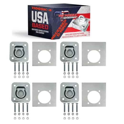
Attachment rings: use D-rings when alignment with a curved surface is required, O-rings when rotation is needed, rectangular rings when webbing must lay flat. Internal ring diameter should be 1.7–2.5× webbing width to avoid acute bending and wear; choose 316 stainless steel in wet or salty environments, plated carbon steel for light indoor applications. Use washers or load-distributing plates under rivets or bolts when attaching rings to plastic or composite panels.
Fasteners and inspection: use solid rivets or M4–M6 countersunk bolts with lock nuts on high-load anchor points; specify shear-rated rivets with head diameters at least 1.5× webbing width. Perform a static test at 2× expected operational load for 1 minute after assembly, then cycle-adjust the hardware 50 times to check for slippage. For reference product comparisons and an unrelated cleaning tool review see best backpack vacuum for pet hair.
Anchor placement and load-bearing stitching
Overlap webbing at least 100 mm (4 in) and secure with a 50×50 mm stitched box plus internal diagonal X; finish each short edge with a triple bar-tack spaced 6–8 mm apart.
Use bonded nylon or polyester heavy-duty thread (commercially labelled #69 or equivalent). Set stitch length to 3–4 mm when sewing heavy weaves like 500D Cordura; switch to 2.5–3 mm stitch length when sewing leather reinforcement patches. Select an industrial needle sized 110/18 or 120/19 for multilayer assemblies.
Place each anchor centered over structural elements such as the internal frame channel or a reinforced vertical seam. Keep the top edge of the stitched box at least 10–15 mm away from zipper tape and at least 25–30 mm from the outer edge of the panel to reduce seam tear-out. On curved panels, add a doubled reinforcement patch sized 100×100 mm beneath the anchor.
Sew sequence: two parallel straight rows spaced 4–6 mm apart; perimeter box; two diagonals crossing at the center; then bar-tacks at both short ends. When a bartack machine is available, set bartack length to 6–12 mm and run 3–5 passes per end. On domestic machines, mimic a bartack by sewing multiple tight zigzag passes (zigzag width 4–5 mm, stitch length 1–2 mm).
Use a reinforcement patch of the same textile or 1.6–2.0 mm leather sized at least 1.5× the stitched box dimensions. Bond the patch with a contact adhesive (examples: Barge All-Purpose, neoprene-based glue), clamp under weight until cured, then stitch through both layers. Where peak loads exceed 500 N, add metal rivets or large-diameter washers; install two rivets per anchor spaced 12–20 mm apart and centered inside the stitched box.
Validate anchors by applying a static load equal to 1.5× the expected maximum carry weight and then cycling the load 500 times through a 30° motion to detect stitch relaxation or tape slippage. Acceptable limits: less than 10% elongation of stitched lines and no thread fraying. Replace any anchor that fails either criterion and reseal cut thread ends with a low-odor seam sealer.
Reference: how to get scrubber warframe


